Wednesday, 30 July 2014

TEA5767 FM Radio Receiver with Arduino and LM386 Amplifier Part 2


I spent the week playing around with how the radio was working, I wasn't horribly impressed with how it was working after my last post. I think I've pretty much nailed it for what I want to do, I even fixed a few kinks. I do strongly recommend you check out the post behind this one to see links to where software and design material came from. I also mentioned that the way I mounted the TEA5767 was similar to what another individual did, and here is a link to his blog: http://www.doctormonk.com/2012/03/tea5767-fm-radio-breakout-board-for.html

I've also noticed that this posting has been receiving a lot of attention, and I decided it may not provide enough information for someone trying to replicate it, so I made a quick and dirty paintbrush schematic:
For both pots I used a single turn 10K potentiometer.  You should also tie up the SDA and SCL lines up to 5V with a 4.7K resistor - this module seems to work just fine without it.
I understand the schematic isn't great and should be a CAD drawing, but it's simple enough. I'd urge you to dig up the data sheet for the LM386 to look at the different configurations. Hopefully this schematic will make this post more useful! This is a component of a larger project I'm working on, so hopefully at some point I will have it drawn properly in its entirety.

Because of how mine is done, this will be a daughter board soldered onto a main perf. board.

I'll make a programming note here:
You can see in the picture that I soldered onto the middle pin on the right side of the chip, which is suppose to be LEFT CHANNEL. If you decide you want to mute the RIGHT CHANNEL by adjusting the 3rd byte, they are backwards - you will end up muting the wrong one!! I'm not sure if  the issue is that you're turning off the wrong channel, or if the pins are flipped - if you're running stereo, this could mean you have LEFT AND RIGHT backwards. If you're running mono, like I am here, it won't matter - but I feel this is a fairly large ooops in a data sheet.

One thing I really didn't like about how my first attempt worked was that tuning with a 270 degree potentiometer was horrible. It just doesn't have enough resolution - if you actually tuned the channel you wanted, it would weave in and out of it, making it pretty intolerable. The solution I came up with (and this is really because I wanted to keep the number of knobs and buttons to a minimum) was to use the ADC to use different areas of the knob to achieve different results.

To the left you can see the scheme I used to control the tuning. It was a little weird at first, but I seem to have gotten the hang of it. If the knob is pointed up, nothing happens. Turn it a little to the left and it decreases by 100KHz, Turn it further, it decreases by 1MHz. It's buffered by a 300ms delay, which you could tweak to your tastes. I'm not in love with it, but it seems to work well for using the materials I have and getting it to tune in a satisfactory way. I will likely use the same method for setting the time on the clock portion of this project.

Here is what some of  you may have been skimming for, the code:

#include <Wire.h>

unsigned char frequencyH;
unsigned char frequencyL;

unsigned int frequencyB;
double frequency;
double tunerFrequency;

void setup()
{
  Wire.begin();
  frequency = 95.9; //A fancier approach would be to store this in EEPROM and retrieve last channel ;)
  Serial.begin(9600);
  setFrequency();
}

void loop()
{
  int reading = analogRead(0);
  //Serial.println(reading); //Shows the adc position - setting it to 512 will point "up" so you can attach a knob
  if (reading <= 410 || reading >= 614) checkTuner(); //only check tuning if tuning knob leaves rest area
}

void checkTuner()
{
  int currentReading = analogRead(0);
  if (currentReading <= 205) frequency = frequency--; //Tune back by 1MHz
  else if (currentReading >= 206 && currentReading <= 410) frequency = frequency - 0.1; //Tune back decimal
  else if (currentReading >= 614 && currentReading <= 819) frequency = frequency + 0.1; //Tune forward decimal
  else if (currentReading >= 820) frequency = frequency ++; //Tune forward by 1MHz
  else frequency = frequency; //If something unexpected happens, this will buffer it out
  if (frequency < 88.0) frequency = 88.0; //make sure it doesn't tune too low *Band limits can be adjusted
  if (frequency > 108.0) frequency = 108.0; //make sure it doesn't tune too high
  delay(300);// this delay will only occur if the main loop makes it into this function
  Serial.println(frequency);//only prints frequency while being tuned
  setFrequency();
}

void setFrequency()
{
  tunerFrequency = ((int)(frequency * 10)) / 10.0; //fun use of a cast!
  frequencyB = 4 * (tunerFrequency * 1000000 + 225000) / 32768;
  frequencyH = frequencyB >> 8;
  frequencyL = frequencyB;
  Wire.beginTransmission(0x60);
  Wire.write(frequencyH);
  Wire.write(frequencyL);
  Wire.write(0x1A);//0001 1010 -highside injection, forced mono, "right channel" muted, *PINOUT AND 3RD BYTE HAVE CHANNELS SWAPPED
  Wire.write(0x10);//Set for US and Europe band
  Wire.write(0x00);
  Wire.endTransmission();
}


I won't take credit for this in its entirety, between the link I posted above and a blog mentioned in the previous post, is where some of the work came from. You will want to open the serial monitor window in your Arduino IDE to see the frequency. I implemented my tuning method in the checkTuner function. I also tweeked out the setFrequency function, it seems to have fixed an issue I was having with the tuning drifting by 0.1MHz (I don't know why). I also changed that it only sends a message out to the I2C bus only after a change is requested by the checkTuner function - I was getting a ticking sound from it constantly communicating ~200ms. So I have it tuning better and less clicking. I also adjusted some of the data bytes to better reflect my needs. I found a detailed data sheet here:
http://www.voti.nl/docs/TEA5767.pdf 

The one last issue I had was trying to get it to scan for channels. I never got it to work properly, if you have it sorted out, let me know! 

So yeah, check out the video for the demonstration, and stay tuned to see where this project ends up. I hope this helped if you were looking for guidance!

If you want to see this project with a real time clockadded to it, check out a more recent blog which uses the DS3231 RTC combined with the project you just read about here: Arduino + DS3231 Real Time Clock

Monday, 21 July 2014

TEA5767 FM Radio Receiver with Arduino and LM386 Amplifier

Moving along with the clock radio project, I made a hardware prototype of the radio component!

Here is the YouTube video that gives a quick demonstration and a quick overview:

See the second post on this topic for diagram and improved code: TEA5767 FM Radio Receiver with Arduino Part TWO

Basically, the goal of this was to get a radio module to work with a microcontroller, and also decide on the amplifier configuration. In the video you can see it hooked up to a small 8 ohm speaker, and it sounds decent - and it will sound better once it is in an enclosure.

I purchased new potentiometers, the TEA5767 modules and the LM386 amplifiers off of eBay. Waiting for the components is a little frustrating, however the venders in China are low cost and very friendly - I've only ever had one issue, and it was the mail systems fault.


The most difficult stage of the project was trying to get the TEA5767 module to be useable. It is really really small. Don't order just one of these, you will likely make a mistake - I bought two of them for less than $4.00.


Attaching wires to this was tricky. This was my first attempt. in the bottom left, you can see a surface mount component is missing.. while attaching the wire with a soldering iron, I accidentally had solder run up onto the board and the component started to float - it was way too small to re-attach. The device no longer functions correctly, maybe I'll try to figure out what the component was at some point and fix it, but for less than two bucks, I'll let it go. Another issues I had, and this happened on both my modules, the bottom right pin is VCC, and I accidentally bridged it to the case of the crystal, which caused a short - easily fixed.

The second attempt was a little more involved, but yielded much better results! I used a scrap of protoboard and some pin headers to hold the chip. This technique was very similar to what I think I say someone else do while I was looking around on Google (I forget where). Basically, I just used a small piece of wire and threaded it through and pushed it against the side of the board and I soldered it from the side so I wouldn't damage components. I pushed the plastic down on the pin headers to get as much length as possible on the pins and dripped the header in. The wires are tacked onto the pins on the backside NOTE: You will need a clamp of some sort to dissipate heat when soldering the wires to the pins, as the heat will otherwise separate your wire from the side of the chip (I used a set of self clamping tweezers). One of the reasons why my breadboard was such a mess was because it was built to hold my first attempt, and the 2nd attempt didn't fit quite so nicely.
The first attempt would have taken less space, the second attempt didn't fit on the breadboard very well. Since I only had two of these, this will be how the module exists in my final clock project.
Most of the information I gathered on using the TEA5767 with an Arduino was on another blog:
http://www.electronicsblog.net/arduino-fm-receiver-with-tea5767/
This blog contains lots of information, including some information from the datasheet, it's highly readable!


Also on the breadboard is the LM386 amplifier. The speaker and amplifier circuit are all running off of the 5v rail on the Arduino board, which also goes to show how little power this takes. The schematic I used I found on another blog, Hack A Week, which I follow on YouTube regularly. His LM386 blog is found here:
http://hackaweek.com/hacks/?p=131
The schematic shows a 10uf capacitor to optionally increase gain, this circuit had plenty of overhead without it, so I didn't include it. I did the "bass boost" filter, but used 0.047uf rather than 0.033uf - I personally liked the sound more.


Here is a picture of on of my Arduino development boards for fun. You can see I'm only using a few wires. The Arduino had two wires supplying power to the breadboard, 2 wires for the I2C and one wire to receive ADC (analog to digital data) from the potentiometer being used as the tuner.


So yeah, watch the video at the top to see what's going on here. In the near future, I hope to have the tubes soldered onto a board so I can start moving ahead with the build. I have a few concerns about trying to multiplex 6 tubes with the same microcontroller that is running devices on an I2C bus, I might use two...  I don't know, we'll see. But anyway, cheers!

Here's a picture of what this project is doing to my poor workbench. A mess is a sign of genius, right?
Good luck with your project!

Friday, 11 July 2014

Superheterodyne Shortwave Receiver


This will be a very short post showcasing a Telecommunications project that I completed for school. I'm reluctant to share any of the specs, as the circuit board and specifications were developed by one of the faculty at the school, and I don't really feel that they are mine to share. BUT, feel free to take a look at it!


This entire project is based around the TDA1572 IC, which is an older chip designed for AM radio receivers. In this project, the radio is tuned to function between ~ 9-12MHz. It does work well, and late at night I can listen to international transmissions! I'm listening to China Radio International while writing this! It also feature an MPF102 JFET and an LM386 OPAMP for the amplification of the signal. It also has 3 hand wound toroids.

The electronics are housed in this cigar box, which at one point contained 25 Luis Martinez Ashcroft Corona cigars (A year in the humidor and they really have a nice medium taste, I like them with a drink of wine or Scotch at night). This was the perfect size for this radio project. Buy your box here!


This view is to show off the speaker. It's a clear plastic waterproof speaker I picked up at the surplus store, I may replace it later, but it works fine. On the bottom left you can see a banana terminal, which I'm using to insert the antenna. Currently I'm using a length of scrap clothes line which works very well. I clip the antenna to my clothes line and reel it out, which works great for a temporary whip antenna, it's about 35'. A longer antenna would be better for this radio, but it works quite well!


While I was making my youtube video, my cat decided to come help.


Here is a picture of the guts. The board was created for a class to use, which included instructions. The TDA1572 was an SMD chip chip soldered on its own board, then that board was soldered using headers to the main board.
A lot of the schematic can be found on the data sheets provided by the futurlec website, the data sheet is very detailed, and has lots of room for deciding how you want to build your radio!
You can can also see the potentiometers I hot glued in (the box was too thick to set the nut). The potentiometers are for volume, fine tune, coarse tune. You can also see a few marrettes, which are used to connect the wallwart to the board. The board has a 7805 regulator.

For a handmade project, I think it looks pretty slick!

Okay, so what's this superheterodyne talk about? The TDA1572 IC allows for a lot of the work to be integrated into one chip. In most hobby radios, or super old radios, a system called RTF (Radio Tuned Frequency) is used, which usually uses a ferrite road wound with a given number of turns of magnet wire, and a costly variable capacitor, which then resonates with the desired frequency, and that signal is amplified. The superheterodyne takes a signal and brings it down to the IF (intermediate frequency) or "working frequency" and then does its work. This chip requires relatively few components for what it is doing!

If you are interested in the work being done on the signal in a superheterodyne receiver, check out the wikipedia page, it is very descriptive and well written.
I am very impressed with how radio has progressed. I intend to build an FM receiver into my next project, and the number of external components is almost none! That project will just drop the FM IC onto an I2C bus, and away it goes. I do think in the future I will pick up a vintage radio and claim the parts to build an RTF style receiver that goes even lower down so I can explore some of the transmissions happening further down, but that might be a while before that happens...

Anyway, for anyone who is interested, I'm still working on my IV-9 clock, and very recently I made the small step of getting my two tube counter to work on a PIC18F44K22! Which I plan on the final clock radio to run entirely on one PIC18F45K22 microcontroller. I'm still toying with it, hopefully I'll have a 6 tube board going soon.
 Here are the two tubes displaying 27, while you can see it toggling between the two tubes on the scope. I had a few issues with the software going from Arduino to Microchip, but yeah, works fine.


Anyway, cheers, have a good one!

Tuesday, 1 July 2014

IV-9 Clock - Prototyping!

IV-9 tubes are vintage Russian tubes which were a precursor to 7 segment LED displays. They are now sold on the internet along with other display tubes mostly for hobby applications. Most people are turning them into clocks, which I will also be doing - but I'm going to take it up a notch, and hopefully add a radio too!


Each of these tubes have 9 pins on them. 7 are for the segments, one is for a decimal place and the final pin is a common pin. I've decided to build my own hardware and to use a microcontroller to multiplex the tubes, or in other words, only one tube will be on at a time, and a different number pattern will be sent on the same data lines while a certain tube is selected. I did some research on this, and many people simplified (not necessarily a bad thing) their projects by using chips meant for driving LED 7 segment displays or using chips meant for building clocks.

Before I solder anything or get too far ahead of myself, I wanted to trouble shoot and sort out issues on a solderless bread board. I only put two tubes on, as these things take up a lot of space and use a lot of components. I'm also using an Arduino to speed up the prototyping. The final clock will hopefully be using a PIC18.


On this prototype all the inputs drive transistors, so the only component between the Arduino and the transistor base is a current limiting resistor. I'm using 2N3906 transistors for driving the characters, and 2N3904 on the tube selection (common pins on the tube).

I used 10K resistors on the base of the 2N3906's - they're only about 20mA's per segment.
I used 1K resistors on the base of the 2N3904's as the common pin on the tubes can possibly be handling each segments plus a decimal or roughly 160+mA.

The sad news is that I originally had segments from one tube bleeding into the same segment on the other tube, so I ended up installing diodes on each pin for each segment on each tube. 8 diodes a tube, I am not looking forward to soldering this board. It also drops the voltage down a bit, 5V-0.7V=4.3V, which is fine, the data sheet says a max of 4.5V anyway.

I would like to post a schematic, but I will need some serious time to figure out how to lay it out, things got pretty busy fairly quickly!


My 6 tube board will have the following materials:
6     IV-9 tubes
8     2N3906 Transistors
6     2N3904 Transistors
48   1N4007 Diodes
8     10K resistors
6     1K resistors

These parts were selected because I already had them, a lot of different variations could be used.


This code sample doesn't really have anything to do with what I'll have as a final product, I just used it for testing, but hopefully it will be of use to someone. Also - I was playing around with this, and stuffed some junk code in to simulate another 4 tubes being put in, and I had some stuttering issues, so I ended up completely removing the delays. I'm curious to see how changing the clock speed on my PIC18 will impact the tube intensity, which I have started porting this code over to it. Another concern I have is that when I have I2C devices attached, will they cause enough delay to stutter the tubes? I guess I'll find out!

/*
TEST SOFTWARE FOR 2 MULTIPLEXED IV-9 TUBES - REVISED
THIS IS TEST SOFTWARE AND WAS WRITTEN QUICKLY WITHOUT THE INTENT OF EXPANDING ON IT LATER,
IT IS NOT INTENDED AS A FINE CODING EXAMPLE.

JARRET CHESSELL
JULY 2nd 2014
http://awesomejarret.blogspot.ca/

OBJECTIVE IS TO TEST HARDWARE TO ENSURE OPERATION AND DEBUG HARDWARE
8 PNP 2N3906 TRANSISTORS ON CHARACTER BUS (ACTIVE LOW)
2 NPN 2N3904 TRANSISTORS ON TUBE SELECT BUS (ACTIVE HIGH)

*********************************************************************
DESCRIPTION:
WILL COUNT FROM 0-99 ON TWO IV-9 TUBES AT APPROX 1 SEC INTERVALS
COUNTER WILL ROLL OVER ONCE IT REACHES THE END.
BASICALLY A SUPER COMPLEX EGG TIMER
*********************************************************************

*/

//initialize an array which holds the patterns for numbers 0-9
byte numberPattern[] = {0x84, 0x9F, 0xA8, 0x89, 0x93, 0xC1, 0xC0, 0x8F, 0x80, 0x83, 0xFF};

//initialize counters to 0 with global scope
byte tensCounter = 0;//counts up for tube one
byte onesCounter = 0;//counts up for tube two
unsigned int loopCounter = 0; //delay counter

void setup() {
  //only thing done here is setting first ten pins to output and turning everything off
  PORTD = 0xFF; //PORTD is active low character bus -8bit
  PORTB = PORTB & 0xFC; //we're only manipulating the 2 lsb's, others are left unchanged
  for (byte i = 0; i < 10; i++){
    pinMode(i, 1);
  }
}

void loop() {
    if (loopCounter >= 500){ //chose 500, as each tube gets a 1ms delay, so should increment ~1sec
    loopCounter = 0;
    onesCounter++;
  }

  if (onesCounter >= 10) {
    onesCounter = 0;
    tensCounter++;
  }

  if (tensCounter >= 10) tensCounter = 0;

  PORTB = PORTB & 0xFC; //common pins off on both tubes
 
  PORTD = numberPattern[tensCounter]; //insert desired pattern and assign it to port
  PORTB = PORTB | 0x01; //"tens" tube common pin turned back on
  delay(1);
 
  PORTB = PORTB & 0xFC; // common pins off on both tubes
 
  PORTD = numberPattern[onesCounter];//insert desired pattern and assign it to port 
  PORTB = PORTB | 0x02; //"ones" tube common pin turned back on
  delay(1);
  loopCounter++;
}


In the YouTube video at the top I also gave mention to a website that I've ordered stuff from in the past, and many of the components I used I purchased from them. YourDuino.com I've used them more than once, and it's a cost effective away to bulk up your parts for prototyping!

Tuesday, 17 June 2014

Building Your Own Bench Power Supply Part Deux

And I'm back!
DEMONSTRATION VIDEO

Bench power supply is finished!


ALSO, look at my previous blog to see my first part of this project.


The end result is a bench power supply with a 5v, 12v and variable output. The variable side goes from ~1.25 to 16.5v. It is based on the popular voltage regulator packages 7805, 7812, LM317. These are all linear regulators, which work well, but are not efficient. Both the 7805 and 7812 can supply 1 amp, and the 317 can supply 1.5 amps, but due to the nature of these things, amps out = amps in, which eats up a little more juice than you would usually like for current heavy projects, but again, this is for working on the bench, so it's more than enough for my needs.

This is the rough sketch I made to get things rolling. The spill looking red tint at the bottom is not wine, it's liquid that leaked out of grease gun which is full of red grease which dripped when it got super warm in my garage. Two differences between this and the final are that I never did find a transformer I liked, so It's still using a laptop PSU (I haven't put a fuse in either because of this), and also, rather than a 5k pot (I had a 5k, but it burned up while I was playing around), I used a 10k, which didn't give much resolution, and the top 2/3's of its range didn't impact output, so I put it in series with a 1k pot, which gave me a nice fine adjust - which I might encourage you to do even if you have the 5k. Here is the LM317 schematic lifted from the TI data sheet:

I also included 3300uF caps at the front end of each rail to help isolate each output. I also am planning to one day find a suitable transformer and install it, so the caps will clean up any ripple. The ideal transformer I would like to see go in this would be a 75VA with a 24V secondary. I even included a bridge rectifier on the board in anticipation of one day finding one! (Having it there with a DC supply going in won't hurt anything, but I am losing 1.4V across the diodes in the the rectifier.
Other additions that went on top were a little voltage meter. I originally bought a voltage/amp meter off of eBay but it got lost for a few months, and when it finally did show up, the amp range was out to lunch, so I bought one for a few bucks at a local new supplier - http://www.elelsu.com/, I also purchased some small heat sinks there for the TO-220 package voltage regulators as well as the project board for soldering it all together. The 3300uF caps, the bridge rectifier and the knobs for the pots came off of eBay. I also out of frustration and lack of patience used a 12v cooling fan, rather than beefy heat sinks and relying on convection to cool them (These things get ridiculous hot when you have a large change of voltage and you're pulling a lot of current).

Okay, let's put this thing together!

This is as far as my prototyping went. At this stage of the bread boarding, I wanted to make sure everything was stable. I originally dropped a 12v regulator in, then followed it with a 5v regulator behind it - This is a good idea because then the 5v wouldn't have as much of a step from the input voltage down to the 5 volts. This is also a bad idea because the 7812 I'm using is rated for one amp, and already running a fan, so if I wanted to use them both at the same time, I would be limited to a little less than 900mA between the 5v and 12v rails - On the final board, I dedicated a rail to each so they both have access to about a full amp.
The good news with the fan was that it seemed to fix any heat issues that occurred with the undersized heatsinks.


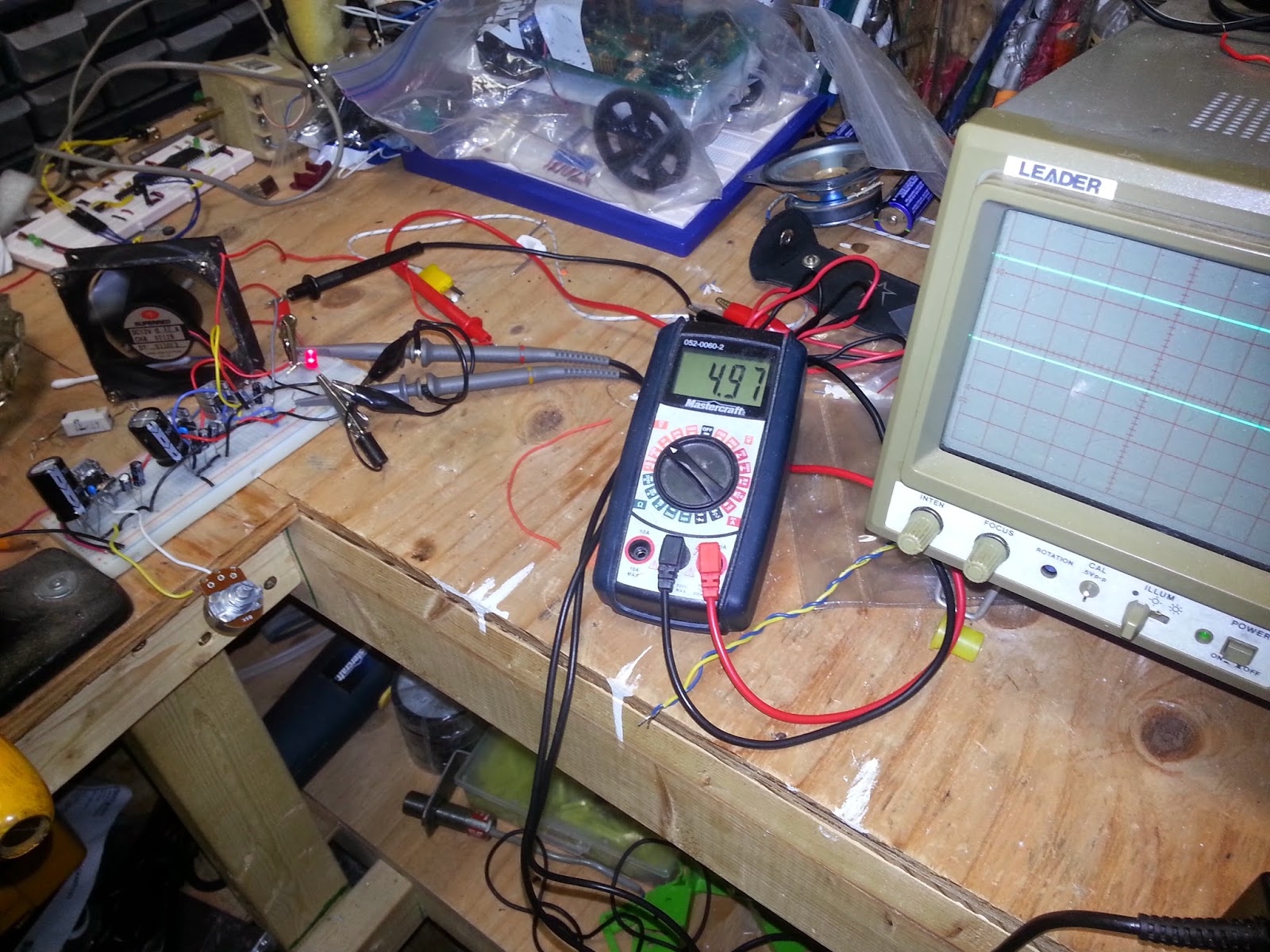
RIPPLE TEST! I also had a little power LED at this stage, which I removed on the final piece, as the always on voltage meter performed the same function. But yeah, great! I was using the multimeter to show me the output on the 5v rail, and the scope was showing the 12v and variable rails. (Scopes are darn handy even as multimeters!)


I started soldering it together onto this prototype board. I'm usually pretty aggressive about testing at every opportunity that I get - and it usually pays off. I ended up having to rework the LM317. The pin out of this regulator doesn't seem to work well with putting it on a board, and I mixed something up, so I'm glad I troubleshot and fixed the problem before I assembled the entire supply. The variable part of this was by far the more challenging part.

Board with soldering finished.

Tested and working!

This is the board when I was done with it trimmed down. Cutting the board was easily done with a steel rule and a carpenters knife. The top screw terminals are for the pots to control variable voltage, the three facing the right are the three different outputs, and the bottom screw terminal excepts the input voltage (not the bridge rectifier directly above it). I'll also mention that I did have to reposition a few thing, I DID NOT get this right the first try.


This is a side view. Notice the small resistor left of the bridge rectifier and in front of the capacitor? It was removed and jumped. I was doing what I do, and I put a heavy load on the supply to see what would happen and.................


This is what happened to it! The purpose of the resistor was to limit the current going in when first turned on - when you first power up something with capacitors, they act as a short, I figured I would put this on to limit the current going to the capacitors when I first flicked it on. It worked great with no load on, but when I tested the supply, all current had to go through this thing. Under my test, I put a 15 ohm ceramic resistor on. Even at 5VDC you end up with 333mA, which doesn't sound like a big deal, but because of these regulators, It pulls 333mA at the input side, in this case ~17 volts. Power = .333mA * 17V = 5.6 watts. This is a 1/4 watt resistor, and she burned. So yeah, not included in final revision. TEST TEST TEST!

So anyway...

Enclosures are expensive online! I tried to find something around the house and turned up nothing. I asked my wife to find something that was plastic and about "yey big" at dollarama. She found this, and at $2.50, I couldn't complain.


This is the enclosure with all the knobs and bits installed in it. This was all done using a drill and a carpenter's knife. The only downside was that I don't have a finger guard for the fan - and these will cut and hurt you if you stick your finger in! I'm sure it will happen eventually. If I come across a finger guard, I'll be sure to add it. I already owned the banana plug posts as I use them for home theatres (which is something I do on the side). I bought a pack of knobs to go on the potentiometers for another project. Power switch was also salvaged from old gear.


This is just me going crazy and driving a bunch of holes into one side to provide an intake for the air being extracted by the fan. Hopefully the position will draw air over the hot components, as well as the transformer if one ever goes in.


Here's a pretty view of everything before it all gets seated and connected in. Pretty fancy!


Everything installed. Everything fits nicely, dollarama has served me well!


Final finished product! It works great, I saved some money! Since I built it, I should also be able to fix it should something ever happen. It turned out to be a nice little project, and I worked pretty hard to make sure the cost was low (I avoided adding features just to keep it simple).
But yeah, if you make one, good luck! Hopefully I provided some guidance or at the very least, stopped you from making a few mistakes! Check out the YouTube video at the top for a demonstration.

The next blog will probably be about a shortwave radio project (just a brief post), but the next major project will be... well.... here is a clue:


Monday, 5 May 2014

Building Your Own Bench Power Supply

After looking around online at expensive bench power supplies, I decided they were often much too costly, and cheaper ones used boring resistor voltage dividers. I decided to set out on my own journey... I probably should have just bought one...

I decided that I would build a bench supply with DC 5v and a variable output as well. I am trying to use as many parts that I already own as possible to reduce cost. I dug through my pile of voltage regulators, and pulled out the trusty old LM7805 for 5v, and the LM317 for Variable. Those regulators are classic and tried and true. The data sheets also contain diagrams for building power supplies, it couldn't get easier! well... no.
It looks like I know what I'm doing, eh? HA!

It looks like it's fine, 15V no ripple...

So, this thread really isn't complete, I'm only half way into the project. Instead of an AC transformer, and bridge rectifier, I tried to fast track by re-purposing an old laptop 18.5v supply. (FAIL). Stepping down directly from that high of a voltage down to 5v produced an insane amount of heat on the LM7805 - it could actually only run with a load on it for a few minutes (1/3 of an amp). On the other side, with the LM317, if I set the voltage to 15v I could hold a full amp for 5-10 minutes without getting some voltage drop and thermal shut down issues.

 Ooops! Melted breadboard and resistor!
(Note the added heat sink on regulator)
This was actually my fault and not the resistor. I was using this 5 watt resistor as a test load. It's 15 ohms, and I was running it at 15 volts as a test load. That's 1 amp and 15 watts... 10 watts more than the ceramic resistor rating - after 20 minutes it became really really hot, I put a heat sensor on it, and it exceeded 300 degrees Celsius! This load had nothing to really do with the operation of the circuit, but it entertained me anyway. 

I still do have heat issues with both regulators going into shut down. I added small heat sinks that helped, but they aren't making the cut. I also need to consider perhaps using two transformers, one dedicated to the 5V rail that is maybe only 9-12 volts. Heat issues with the variable side are also concerning, I'll try tracking down a better heat sink and consider a cooling fan as well. I suspect most the variable supplies you see people make online are not handling much load, or aren't pushed very hard or for very long. The ideal simplistic versions of LM317 supplies don't seem to deal with the issues that arise when you test them. I am very glad I bread boarded this and am working out the kinks slowly.

The main project goal is to have the finished project on a solder board and in an enclosure. I posted this prematurely, but I think posting this will help to prevent me from shelving the project.

Once I have what I feel is the best configuration, I will post a schematic and some pictures.
Stay tuned!

Friday, 21 March 2014

ULN2803 interfaced with a Raspberry Pi

One of the issues with using an ARM based system or a micro-controller such as an Arduino or a Microchip is using the I/O pins to drive any real load, anything other than an LED seems to cause issues. So what do we do? In the case of a Raspberry Pi we have outputs that are only sitting at 3.3v, and conversations on forums seem to point to you not pulling more than 50mA from any one pin. I'd recommend only pulling a few mA if possible, and if you used 8 outputs at 50mA each, that would be 400mA, which just won't work well, something will fry. Anyway, introducing the ULN2803 (link to datasheet). What is it? It's called a "Darlington Array" which consists of a bunch of Darlington pairs, which is two transistors back to back per channel.
(Schematic from datasheet)

It has 8 inputs and 8 outputs arranged neatly so the package is easy to use and works well on a breadboard.
 (Schematic from datasheet)

What do they do? You can attach a secondary supply of a voltage between 0-30VDCs and pull a current of up to 500mA per output (you can gang them together for increased current too). What does this mean? Lots of POWER! Traditionally you would use an NPN transistor, and use a current limiting resistor that you had to determine its value based on the beta characteristics of the transistor, and use diodes to prevent kick back from relays, yadda yadda. This package includes a limiting resistor as well as diodes to prevent fly-back from those pesky collapsing electromagnetic fields on coils. Maybe that was a dramatization, but here is a video demonstration to enjoy:


In the video I complain that the mA's I pulled through are lower than what I calculated. I looked into it more, and it turns out that I can't read - I thought one of the ceramic resistors was 5 ohms, but it was actually 15. So the reading on the multimeter was actually (Vcc - Vbe) / (22ohm + 15ohm) which came out to around 120 mA. I originally thought the ohms would be 27, not 37.

I also prepared a schematic that doesn't show anything too exciting, however, it shows a byte of LED's being driven directly by the GPIO, as well as having a parallel connection to the ULN2803 which is driving more LED's. It isn't terribly exciting, but you can see that a different supply voltage is used for the 2nd set of LED's, and a relay could easily be dropped in, and the voltage could be different as well. 
(Made with Fritzing)

One other thing to pay attention to is that the voltage is being supplied to the components and not sourced (grounding it to the outputs on the ULN2803).
I've also seen some discussion about putting a limiting resistor on the inputs of the ULN2803, and I haven't come to any real solid best practice, so I did the lazy thing and did nothing. 
I would recommend fusing the power supply connection to your chip, and also placing a bypass capacitor between the + and - on the chip: 0.1uF should be fine (104 ceramic code).
Also check out the ULN2003, which is similar, except it has 7 inputs and outputs. These chips can supply small motors and steppers too!

I hoped that helped!