This is a partial write up, I will expand on this soon. I wanted to put a schematic and code up for anyone who was interested in following up the YouTube video I posted about this!
Enjoy! PLEASE NOTE: I often add captions to correct myself or elaborate in these videos, but the text is usually only visible if you watch it on the YouTube website.
A lot of this project was inspired by this page: Cool Magnet Man This is an incredibly valuable resource if you are interested in projects involving magnets and magnetism - I strongly encourage you to read through his website, I've spent a fair amount of time enjoyably reviewing his posts.
I will apologize in advance, the code isn't amazing, the design is a little short changed - but this thing went together really quickly from concept to reality. I will likely have a software revision in the near future, if you find any bugs please let me know so I can improve the next version. This is designed to run from a 9V battery.
ARDUINO CODE:
(Some of the LCD positioning is funny because I was using an odd ball LCD for the breadboard)
IV-9 tubes are vintage Russian tubes which were a precursor to 7 segment LED displays. They are now sold on the internet along with other display tubes mostly for hobby applications. Most people are turning them into clocks, which I will also be doing - but I'm going to take it up a notch, and hopefully add a radio too!
Each of these tubes have 9 pins on them. 7 are for the segments, one is for a decimal place and the final pin is a common pin. I've decided to build my own hardware and to use a microcontroller to multiplex the tubes, or in other words, only one tube will be on at a time, and a different number pattern will be sent on the same data lines while a certain tube is selected. I did some research on this, and many people simplified (not necessarily a bad thing) their projects by using chips meant for driving LED 7 segment displays or using chips meant for building clocks.
Before I solder anything or get too far ahead of myself, I wanted to trouble shoot and sort out issues on a solderless bread board. I only put two tubes on, as these things take up a lot of space and use a lot of components. I'm also using an Arduino to speed up the prototyping. The final clock will hopefully be using a PIC18.
On this prototype all the inputs drive transistors, so the only component between the Arduino and the transistor base is a current limiting resistor. I'm using 2N3906 transistors for driving the characters, and 2N3904 on the tube selection (common pins on the tube).
I used 10K resistors on the base of the 2N3906's - they're only about 20mA's per segment.
I used 1K resistors on the base of the 2N3904's as the common pin on the tubes can possibly be handling each segments plus a decimal or roughly 160+mA.
The sad news is that I originally had segments from one tube bleeding into the same segment on the other tube, so I ended up installing diodes on each pin for each segment on each tube. 8 diodes a tube, I am not looking forward to soldering this board. It also drops the voltage down a bit, 5V-0.7V=4.3V, which is fine, the data sheet says a max of 4.5V anyway.
I would like to post a schematic, but I will need some serious time to figure out how to lay it out, things got pretty busy fairly quickly!
My 6 tube board will have the following materials:
6 IV-9 tubes
8 2N3906 Transistors
6 2N3904 Transistors
48 1N4007 Diodes
8 10K resistors
6 1K resistors
These parts were selected because I already had them, a lot of different variations could be used.
This code sample doesn't really have anything to do with what I'll have as a final product, I just used it for testing, but hopefully it will be of use to someone. Also - I was playing around with this, and stuffed some junk code in to simulate another 4 tubes being put in, and I had some stuttering issues, so I ended up completely removing the delays. I'm curious to see how changing the clock speed on my PIC18 will impact the tube intensity, which I have started porting this code over to it. Another concern I have is that when I have I2C devices attached, will they cause enough delay to stutter the tubes? I guess I'll find out!
/* TEST SOFTWARE FOR 2 MULTIPLEXED IV-9 TUBES - REVISED THIS IS TEST SOFTWARE AND WAS WRITTEN QUICKLY WITHOUT THE INTENT OF EXPANDING ON IT LATER, IT IS NOT INTENDED AS A FINE CODING EXAMPLE.
JARRET CHESSELL JULY 2nd 2014 http://awesomejarret.blogspot.ca/
OBJECTIVE IS TO TEST HARDWARE TO ENSURE OPERATION AND DEBUG HARDWARE 8 PNP 2N3906 TRANSISTORS ON CHARACTER BUS (ACTIVE LOW) 2 NPN 2N3904 TRANSISTORS ON TUBE SELECT BUS (ACTIVE HIGH)
********************************************************************* DESCRIPTION: WILL COUNT FROM 0-99 ON TWO IV-9 TUBES AT APPROX 1 SEC INTERVALS COUNTER WILL ROLL OVER ONCE IT REACHES THE END. BASICALLY A SUPER COMPLEX EGG TIMER *********************************************************************
*/
//initialize an array which holds the patterns for numbers 0-9 byte numberPattern[] = {0x84, 0x9F, 0xA8, 0x89, 0x93, 0xC1, 0xC0, 0x8F, 0x80, 0x83, 0xFF};
//initialize counters to 0 with global scope byte tensCounter = 0;//counts up for tube one byte onesCounter = 0;//counts up for tube two unsigned int loopCounter = 0; //delay counter
void setup() { //only thing done here is setting first ten pins to output and turning everything off PORTD = 0xFF; //PORTD is active low character bus -8bit PORTB = PORTB & 0xFC; //we're only manipulating the 2 lsb's, others are left unchanged for (byte i = 0; i < 10; i++){ pinMode(i, 1); } }
void loop() { if (loopCounter >= 500){ //chose 500, as each tube gets a 1ms delay, so should increment ~1sec loopCounter = 0; onesCounter++; }
if (onesCounter >= 10) { onesCounter = 0; tensCounter++; }
if (tensCounter >= 10) tensCounter = 0;
PORTB = PORTB & 0xFC; //common pins off on both tubes
PORTD = numberPattern[tensCounter]; //insert desired pattern and assign it to port PORTB = PORTB | 0x01; //"tens" tube common pin turned back on delay(1);
PORTB = PORTB & 0xFC; // common pins off on both tubes
PORTD = numberPattern[onesCounter];//insert desired pattern and assign it to port PORTB = PORTB | 0x02; //"ones" tube common pin turned back on delay(1); loopCounter++; }
In the YouTube video at the top I also gave mention to a website that I've ordered stuff from in the past, and many of the components I used I purchased from them. YourDuino.com I've used them more than once, and it's a cost effective away to bulk up your parts for prototyping!
ALSO, look at my previous blog to see my first part of this project.
The end result is a bench power supply with a 5v, 12v and variable output. The variable side goes from ~1.25 to 16.5v. It is based on the popular voltage regulator packages 7805, 7812, LM317. These are all linear regulators, which work well, but are not efficient. Both the 7805 and 7812 can supply 1 amp, and the 317 can supply 1.5 amps, but due to the nature of these things, amps out = amps in, which eats up a little more juice than you would usually like for current heavy projects, but again, this is for working on the bench, so it's more than enough for my needs.
This is the rough sketch I made to get things rolling. The spill looking red tint at the bottom is not wine, it's liquid that leaked out of grease gun which is full of red grease which dripped when it got super warm in my garage. Two differences between this and the final are that I never did find a transformer I liked, so It's still using a laptop PSU (I haven't put a fuse in either because of this), and also, rather than a 5k pot (I had a 5k, but it burned up while I was playing around), I used a 10k, which didn't give much resolution, and the top 2/3's of its range didn't impact output, so I put it in series with a 1k pot, which gave me a nice fine adjust - which I might encourage you to do even if you have the 5k. Here is the LM317 schematic lifted from the TI data sheet:
I also included 3300uF caps at the front end of each rail to help isolate each output. I also am planning to one day find a suitable transformer and install it, so the caps will clean up any ripple. The ideal transformer I would like to see go in this would be a 75VA with a 24V secondary. I even included a bridge rectifier on the board in anticipation of one day finding one! (Having it there with a DC supply going in won't hurt anything, but I am losing 1.4V across the diodes in the the rectifier.
Other additions that went on top were a little voltage meter. I originally bought a voltage/amp meter off of eBay but it got lost for a few months, and when it finally did show up, the amp range was out to lunch, so I bought one for a few bucks at a local new supplier - http://www.elelsu.com/, I also purchased some small heat sinks there for the TO-220 package voltage regulators as well as the project board for soldering it all together. The 3300uF caps, the bridge rectifier and the knobs for the pots came off of eBay. I also out of frustration and lack of patience used a 12v cooling fan, rather than beefy heat sinks and relying on convection to cool them (These things get ridiculous hot when you have a large change of voltage and you're pulling a lot of current).
Okay, let's put this thing together!
This is as far as my prototyping went. At this stage of the bread boarding, I wanted to make sure everything was stable. I originally dropped a 12v regulator in, then followed it with a 5v regulator behind it - This is a good idea because then the 5v wouldn't have as much of a step from the input voltage down to the 5 volts. This is also a bad idea because the 7812 I'm using is rated for one amp, and already running a fan, so if I wanted to use them both at the same time, I would be limited to a little less than 900mA between the 5v and 12v rails - On the final board, I dedicated a rail to each so they both have access to about a full amp.
The good news with the fan was that it seemed to fix any heat issues that occurred with the undersized heatsinks.
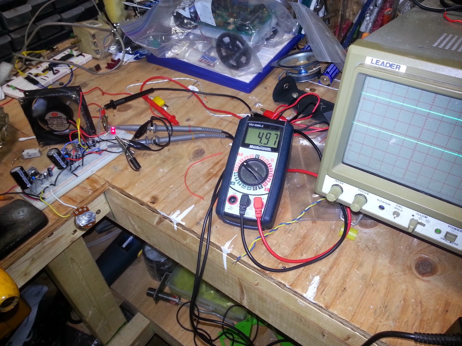
RIPPLE TEST! I also had a little power LED at this stage, which I removed on the final piece, as the always on voltage meter performed the same function. But yeah, great! I was using the multimeter to show me the output on the 5v rail, and the scope was showing the 12v and variable rails. (Scopes are darn handy even as multimeters!)
I started soldering it together onto this prototype board. I'm usually pretty aggressive about testing at every opportunity that I get - and it usually pays off. I ended up having to rework the LM317. The pin out of this regulator doesn't seem to work well with putting it on a board, and I mixed something up, so I'm glad I troubleshot and fixed the problem before I assembled the entire supply. The variable part of this was by far the more challenging part.
Board with soldering finished.
Tested and working!
This is the board when I was done with it trimmed down. Cutting the board was easily done with a steel rule and a carpenters knife. The top screw terminals are for the pots to control variable voltage, the three facing the right are the three different outputs, and the bottom screw terminal excepts the input voltage (not the bridge rectifier directly above it). I'll also mention that I did have to reposition a few thing, I DID NOT get this right the first try.
This is a side view. Notice the small resistor left of the bridge rectifier and in front of the capacitor? It was removed and jumped. I was doing what I do, and I put a heavy load on the supply to see what would happen and.................
This is what happened to it! The purpose of the resistor was to limit the current going in when first turned on - when you first power up something with capacitors, they act as a short, I figured I would put this on to limit the current going to the capacitors when I first flicked it on. It worked great with no load on, but when I tested the supply, all current had to go through this thing. Under my test, I put a 15 ohm ceramic resistor on. Even at 5VDC you end up with 333mA, which doesn't sound like a big deal, but because of these regulators, It pulls 333mA at the input side, in this case ~17 volts. Power = .333mA * 17V = 5.6 watts. This is a 1/4 watt resistor, and she burned. So yeah, not included in final revision. TEST TEST TEST!
So anyway...
Enclosures are expensive online! I tried to find something around the house and turned up nothing. I asked my wife to find something that was plastic and about "yey big" at dollarama. She found this, and at $2.50, I couldn't complain.
This is the enclosure with all the knobs and bits installed in it. This was all done using a drill and a carpenter's knife. The only downside was that I don't have a finger guard for the fan - and these will cut and hurt you if you stick your finger in! I'm sure it will happen eventually. If I come across a finger guard, I'll be sure to add it. I already owned the banana plug posts as I use them for home theatres (which is something I do on the side). I bought a pack of knobs to go on the potentiometers for another project. Power switch was also salvaged from old gear.
This is just me going crazy and driving a bunch of holes into one side to provide an intake for the air being extracted by the fan. Hopefully the position will draw air over the hot components, as well as the transformer if one ever goes in.
Here's a pretty view of everything before it all gets seated and connected in. Pretty fancy!
Everything installed. Everything fits nicely, dollarama has served me well!
Final finished product! It works great, I saved some money! Since I built it, I should also be able to fix it should something ever happen. It turned out to be a nice little project, and I worked pretty hard to make sure the cost was low (I avoided adding features just to keep it simple).
But yeah, if you make one, good luck! Hopefully I provided some guidance or at the very least, stopped you from making a few mistakes! Check out the YouTube video at the top for a demonstration.
The next blog will probably be about a shortwave radio project (just a brief post), but the next major project will be... well.... here is a clue:
After looking around online at expensive bench power supplies, I decided they were often much too costly, and cheaper ones used boring resistor voltage dividers. I decided to set out on my own journey... I probably should have just bought one...
I decided that I would build a bench supply with DC 5v and a variable output as well. I am trying to use as many parts that I already own as possible to reduce cost. I dug through my pile of voltage regulators, and pulled out the trusty old LM7805 for 5v, and the LM317 for Variable. Those regulators are classic and tried and true. The data sheets also contain diagrams for building power supplies, it couldn't get easier! well... no.
It looks like I know what I'm doing, eh? HA!
It looks like it's fine, 15V no ripple...
So, this thread really isn't complete, I'm only half way into the project. Instead of an AC transformer, and bridge rectifier, I tried to fast track by re-purposing an old laptop 18.5v supply. (FAIL). Stepping down directly from that high of a voltage down to 5v produced an insane amount of heat on the LM7805 - it could actually only run with a load on it for a few minutes (1/3 of an amp). On the other side, with the LM317, if I set the voltage to 15v I could hold a full amp for 5-10 minutes without getting some voltage drop and thermal shut down issues.
Ooops! Melted breadboard and resistor!
(Note the added heat sink on regulator)
This was actually my fault and not the resistor. I was using this 5 watt resistor as a test load. It's 15 ohms, and I was running it at 15 volts as a test load. That's 1 amp and 15 watts... 10 watts more than the ceramic resistor rating - after 20 minutes it became really really hot, I put a heat sensor on it, and it exceeded 300 degrees Celsius! This load had nothing to really do with the operation of the circuit, but it entertained me anyway.
I still do have heat issues with both regulators going into shut down. I added small heat sinks that helped, but they aren't making the cut. I also need to consider perhaps using two transformers, one dedicated to the 5V rail that is maybe only 9-12 volts. Heat issues with the variable side are also concerning, I'll try tracking down a better heat sink and consider a cooling fan as well. I suspect most the variable supplies you see people make online are not handling much load, or aren't pushed very hard or for very long. The ideal simplistic versions of LM317 supplies don't seem to deal with the issues that arise when you test them. I am very glad I bread boarded this and am working out the kinks slowly.
The main project goal is to have the finished project on a solder board and in an enclosure. I posted this prematurely, but I think posting this will help to prevent me from shelving the project.
Once I have what I feel is the best configuration, I will post a schematic and some pictures.
Stay tuned!