DEMONSTRATION VIDEO
Bench power supply is finished!

ALSO, look at my previous blog to see my first part of this project.
The end result is a bench power supply with a 5v, 12v and variable output. The variable side goes from ~1.25 to 16.5v. It is based on the popular voltage regulator packages 7805, 7812, LM317. These are all linear regulators, which work well, but are not efficient. Both the 7805 and 7812 can supply 1 amp, and the 317 can supply 1.5 amps, but due to the nature of these things, amps out = amps in, which eats up a little more juice than you would usually like for current heavy projects, but again, this is for working on the bench, so it's more than enough for my needs.


I also included 3300uF caps at the front end of each rail to help isolate each output. I also am planning to one day find a suitable transformer and install it, so the caps will clean up any ripple. The ideal transformer I would like to see go in this would be a 75VA with a 24V secondary. I even included a bridge rectifier on the board in anticipation of one day finding one! (Having it there with a DC supply going in won't hurt anything, but I am losing 1.4V across the diodes in the the rectifier.
Other additions that went on top were a little voltage meter. I originally bought a voltage/amp meter off of eBay but it got lost for a few months, and when it finally did show up, the amp range was out to lunch, so I bought one for a few bucks at a local new supplier - http://www.elelsu.com/, I also purchased some small heat sinks there for the TO-220 package voltage regulators as well as the project board for soldering it all together. The 3300uF caps, the bridge rectifier and the knobs for the pots came off of eBay. I also out of frustration and lack of patience used a 12v cooling fan, rather than beefy heat sinks and relying on convection to cool them (These things get ridiculous hot when you have a large change of voltage and you're pulling a lot of current).
Okay, let's put this thing together!

The good news with the fan was that it seemed to fix any heat issues that occurred with the undersized heatsinks.
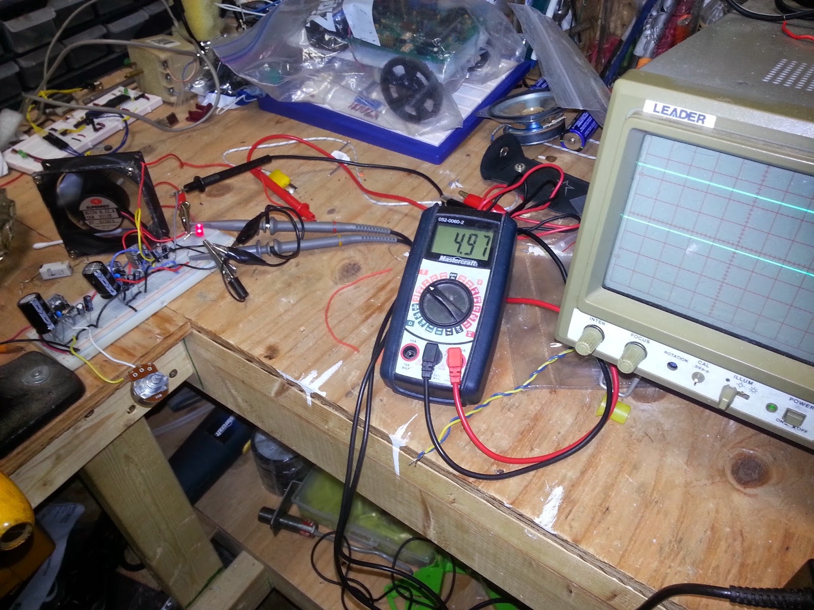
RIPPLE TEST! I also had a little power LED at this stage, which I removed on the final piece, as the always on voltage meter performed the same function. But yeah, great! I was using the multimeter to show me the output on the 5v rail, and the scope was showing the 12v and variable rails. (Scopes are darn handy even as multimeters!)

I started soldering it together onto this prototype board. I'm usually pretty aggressive about testing at every opportunity that I get - and it usually pays off. I ended up having to rework the LM317. The pin out of this regulator doesn't seem to work well with putting it on a board, and I mixed something up, so I'm glad I troubleshot and fixed the problem before I assembled the entire supply. The variable part of this was by far the more challenging part.

Board with soldering finished.

Tested and working!

This is the board when I was done with it trimmed down. Cutting the board was easily done with a steel rule and a carpenters knife. The top screw terminals are for the pots to control variable voltage, the three facing the right are the three different outputs, and the bottom screw terminal excepts the input voltage (not the bridge rectifier directly above it). I'll also mention that I did have to reposition a few thing, I DID NOT get this right the first try.


This is what happened to it! The purpose of the resistor was to limit the current going in when first turned on - when you first power up something with capacitors, they act as a short, I figured I would put this on to limit the current going to the capacitors when I first flicked it on. It worked great with no load on, but when I tested the supply, all current had to go through this thing. Under my test, I put a 15 ohm ceramic resistor on. Even at 5VDC you end up with 333mA, which doesn't sound like a big deal, but because of these regulators, It pulls 333mA at the input side, in this case ~17 volts. Power = .333mA * 17V = 5.6 watts. This is a 1/4 watt resistor, and she burned. So yeah, not included in final revision. TEST TEST TEST!
So anyway...


This is just me going crazy and driving a bunch of holes into one side to provide an intake for the air being extracted by the fan. Hopefully the position will draw air over the hot components, as well as the transformer if one ever goes in.

Here's a pretty view of everything before it all gets seated and connected in. Pretty fancy!

Everything installed. Everything fits nicely, dollarama has served me well!
Final finished product! It works great, I saved some money! Since I built it, I should also be able to fix it should something ever happen. It turned out to be a nice little project, and I worked pretty hard to make sure the cost was low (I avoided adding features just to keep it simple).
But yeah, if you make one, good luck! Hopefully I provided some guidance or at the very least, stopped you from making a few mistakes! Check out the YouTube video at the top for a demonstration.
The next blog will probably be about a shortwave radio project (just a brief post), but the next major project will be... well.... here is a clue:
